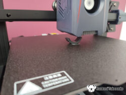
I recently took on the challenge of modernising a Labelmate PM-300-CS dispensing machine. Ideally, I wanted to control this industrial hardware from my computer, so I decided to interface an ESP32 microcontroller. However, there was a major hurdle: the machine operates on 15V logic with noisy motors, while the delicate ESP32 operates on 3.3V. Connecting them directly would instantly fry the ESP32 microcontroller.
Labelmate PM300CS
Labelmate PM300CS DB9 Head Connector
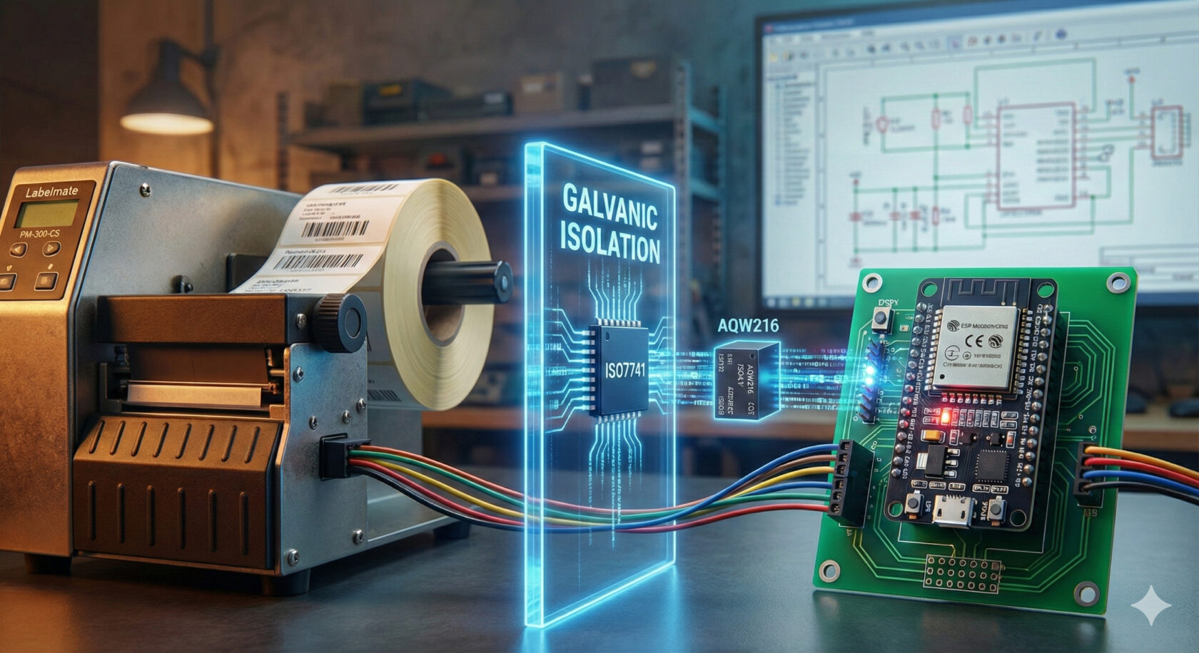
Safety First (Galvanic Isolation)
The core of this project is protection. I needed a circuit that allows data to flow but stops high-voltage spikes and electrical noise.
The Brain & bhe brawn: ISO7741
I chose the Texas Instruments ISO7741, a high-performance digital isolator. It acts as a digital air gap. It automatically converts the machine’s 5V/15V signals to the ESP32’s 3.3V, protecting the MCU from ground loops and motor noise. It requires two separate power sources. The machine side is powered by a LM7805 voltage regulator (stepping down the machine’s 15V to 5V), and the ESP32 side is powered by the USB/3.3V rail.
Signal Conditioning
Encoders (Inputs): The machine sends 15V pulses from its encoders. I used a voltage divider (10kw/4.7kw) to reduce the voltage to ~4.8V before entering the ISO7741.
Start Signal (Output): To tell the machine to Go, I used a Panasonic AQW216 Solid State Relay. It allows the low-power ESP32 to switch the machine’s 15V start line without any physical contact.
Power Stability (The Capacitor Map)
Industrial machines are noisy, to prevent the logic chips from resetting, I placed capacitors strategically:
Input (15V): A 10uF electrolytic capacitor to act as a bulk energy reserve.
Filtering:47nF ceramic capacitors at the regulator output and the ISO7741 power pins to filter out high-frequency noise from the ESP32 WiFi and the machine’s motors.
The final schematic: signal isolation, voltage regulation, and noise filtering.
The Assembly & “The Heat Scare”
Soldering the ISO7741 (SSOP package) was tricky. I had some trouble with the soldering iron and was quite worried I had overheated the chip, potentially causing internal damage.
Before connecting the ESP32, I had to be 100% sure the chip wasn’t shorted internally. If the 15V side leaked to the 3.3V side, the project would be over.
The Testing Protocol: a 3 phase test
This was a 3-phase test to validate the board without risking the microcontroller:
Phase 1: The Smoke Test (Thermal Analysis) I powered only the machine side (15V) and used a thermal camera to inspect the board to ensure no components were overheating due to soldering bridges. I found out the regulator was stable at ~25°C, and the ISO7741 remained cool. Current consumption was a perfect 5mA.
Thermal inspection passed. No hot spots detected on the isolator.
Phase 2 & 3: Logic & Control (MicroPython)
Once safety was confirmed, I connected the ESP32. I used a MicroPython test bench to validate the logic. MicroPython is well-suited for this because it enables rapid hardware testing without compiling C++ code.
Here is the test code I used:
from time import (  # pylint: disable=import-error,no-name-in-module
    sleep,
    sleep_ms,
)
from machine import Pin  # pylint: disable=import-error

print("--- STARTING PM-300 HARDWARE TEST (MicroPython) ---")

# --- PIN CONFIGURATION ---
# Encoder Inputs (ISO7741 Side)
# Do not use Pin.PULL_UP because the ISO7741 already drives voltage (3.3V/0V)
pin_enc_a = Pin(32, Pin.IN)
pin_enc_b = Pin(33, Pin.IN)

# Relay Output (AQW216)
pin_relay = Pin(25, Pin.OUT)
pin_relay.value(0)  # Ensure it starts OFF


# --- TOOL 1: ENCODER MONITOR (PHASE 2) ---
def monitor_encoders():
    print("\n>>> STARTING ENCODER MONITOR")
    print(">>> Move the roller or touch pins 1/2 with 15V.")
    print(">>> Press Ctrl+C to stop.")

    last_a = pin_enc_a.value()
    last_b = pin_enc_b.value()

    try:
        while True:
            curr_a = pin_enc_a.value()
            curr_b = pin_enc_b.value()

            # Only print if something changes
            if curr_a != last_a or curr_b != last_b:
                print(f"Enc A: {curr_a} | Enc B: {curr_b}")
                last_a = curr_a
                last_b = curr_b

            # Short pause to prevent CPU saturation
            sleep_ms(10)

    except KeyboardInterrupt:
        print("\nMonitor stopped.")


# --- TOOL 2: START RELAY TEST (PHASE 3) ---
def test_start(duration_seconds=3):
    print(
        f"\n>>> ACTIVATING RELAY (GPIO 25) FOR {duration_seconds} SECONDS..."
    )
    print(">>> Prepare multimeter on DB9 Pin 7.")

    pin_relay.value(1)  # ON (Closes contact 15V -> Pin 7)
    sleep(duration_seconds)
    pin_relay.value(0)  # OFF

    print(">>> Relay OFF.")


# --- START MENU ---
print("System ready. Choose an option:")
print("1. Type monitor_encoders() and press Enter to test readings.")
print("2. Type test_start() and press Enter to test the 15V output.")
The Results:
Encoder Test: Tapping the 15V input resulted in clean 1 and 0 transitions on the ESP32 console. The isolator works!
Relay Test: The output switched the 15V line perfectly.
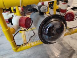
In this post, I describe how my own Arduino Framework for Alioli ROV Submarine Drone works. In my last post about Alioli ROV Submarine Drone, I wrote, “Learn how to Build an...