During our operations, very often, we use a Waterlinked Underwater GPS. This helps us to keep track in 3D of our movements and link video recording’s timing and telemetry to specific places. These experiments were done together with Andalú Sea. Some examples of these 3D tracks are:
Waterlinked GPS – ROV Navigation inside the harbour
Waterlinked GPS – ROV Navigation Open Water
Thanks to this technology, we can position the ROV when it is under the water, but…
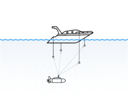
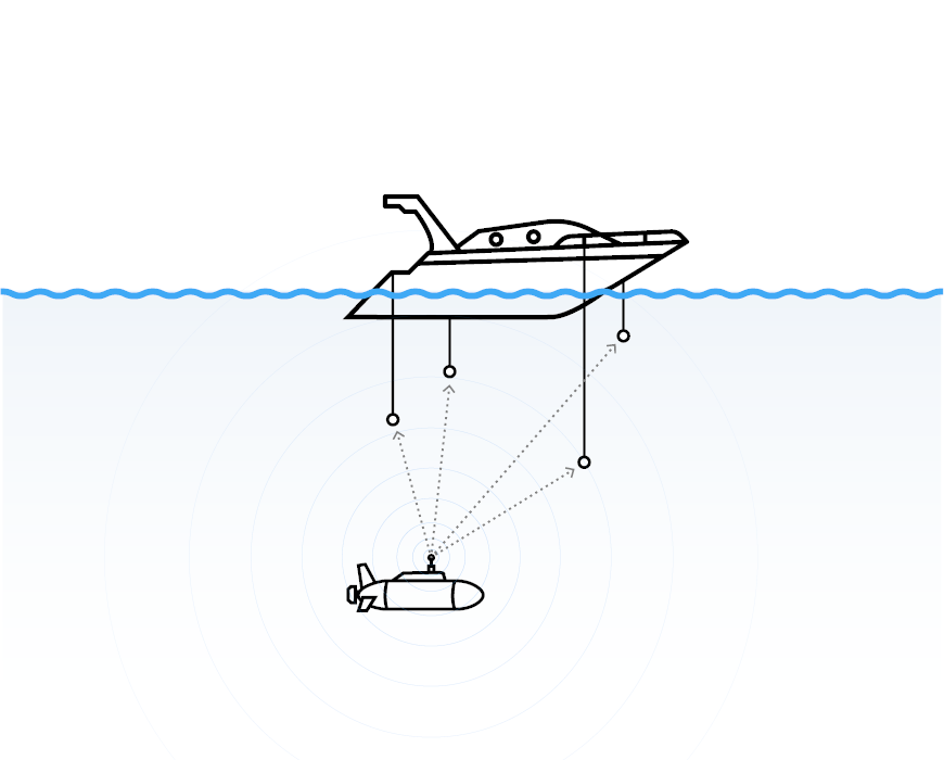
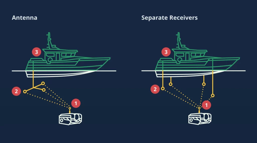
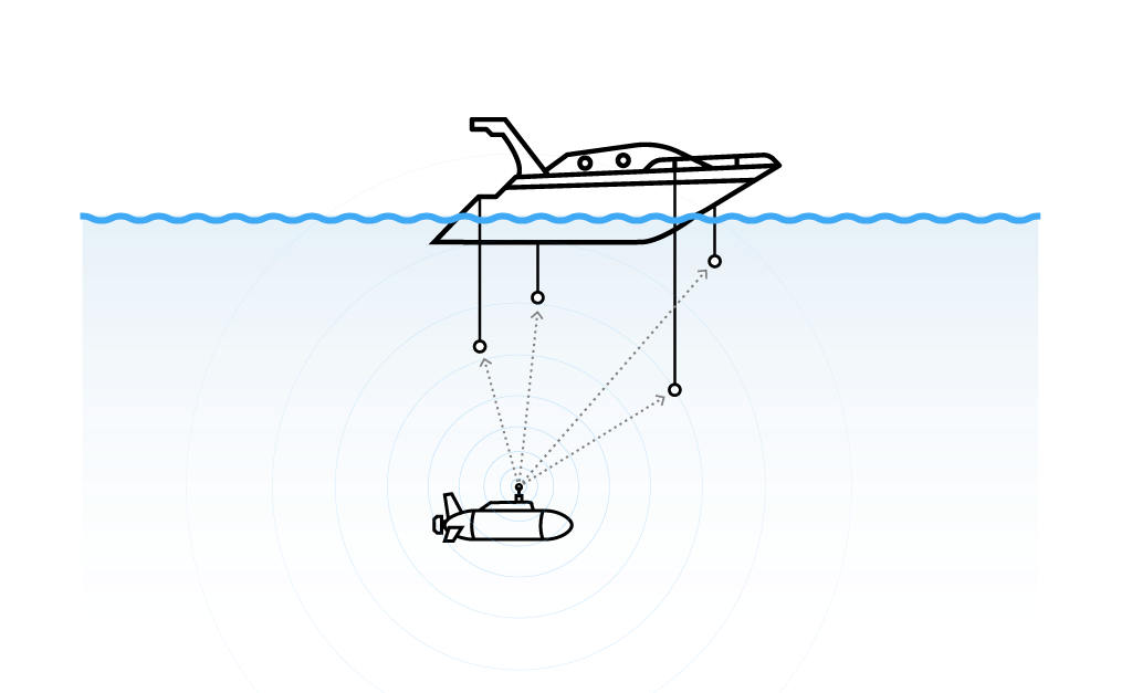
Using the Master Waterlinked GPS System (3), the boat knows the ROV’s position under the water thanks to some pulses that the ROV is sending using a Locator (1) installed. This Locator (1) sends pulses every n-seconds, and those pulses are listened to by the Antenna or Receivers (2), which transmits those pulses to the Master (3).
In general, the Master (3) can compute a lot of information about positioning:
Acoustic data (1+2) will be processed to triangulate the position of the ROV Under the water regarding the Antennas or Receivers (2) position.
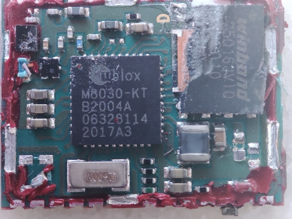
Master (3) reads the Global position from a GPS Chip installed in Master (3). This way, Master (3) can find its position on the Earth.
Rov’s Global Position is inferred from Acoustic Position + Global Position.
How is the acoustic position accurately inferred?
To determine the relationship between Acoustic and Global positioning, the Waterlinked GPS requires pairing the Locator (1) with the Master (3) before getting to the water.
The Locator (1), which has a GPS Chip installed, can synchronize its timing with the available GPS satellites. Once the Locator (1) is synchronized, it sends pulses.
The Master (3) is also synchronized with the available GPS satellites and will start reading those pulses.
When Antenna (2) is set, the system can accurately find out the position of the ROV (distance from the antenna) using synchronized timing. The Master (3) knows when precisely the Locator is sending its pulses. Now it can infer the delay and the distance from each Receiver in the Antenna (2) to the Locator (1).
The rest is just maths.
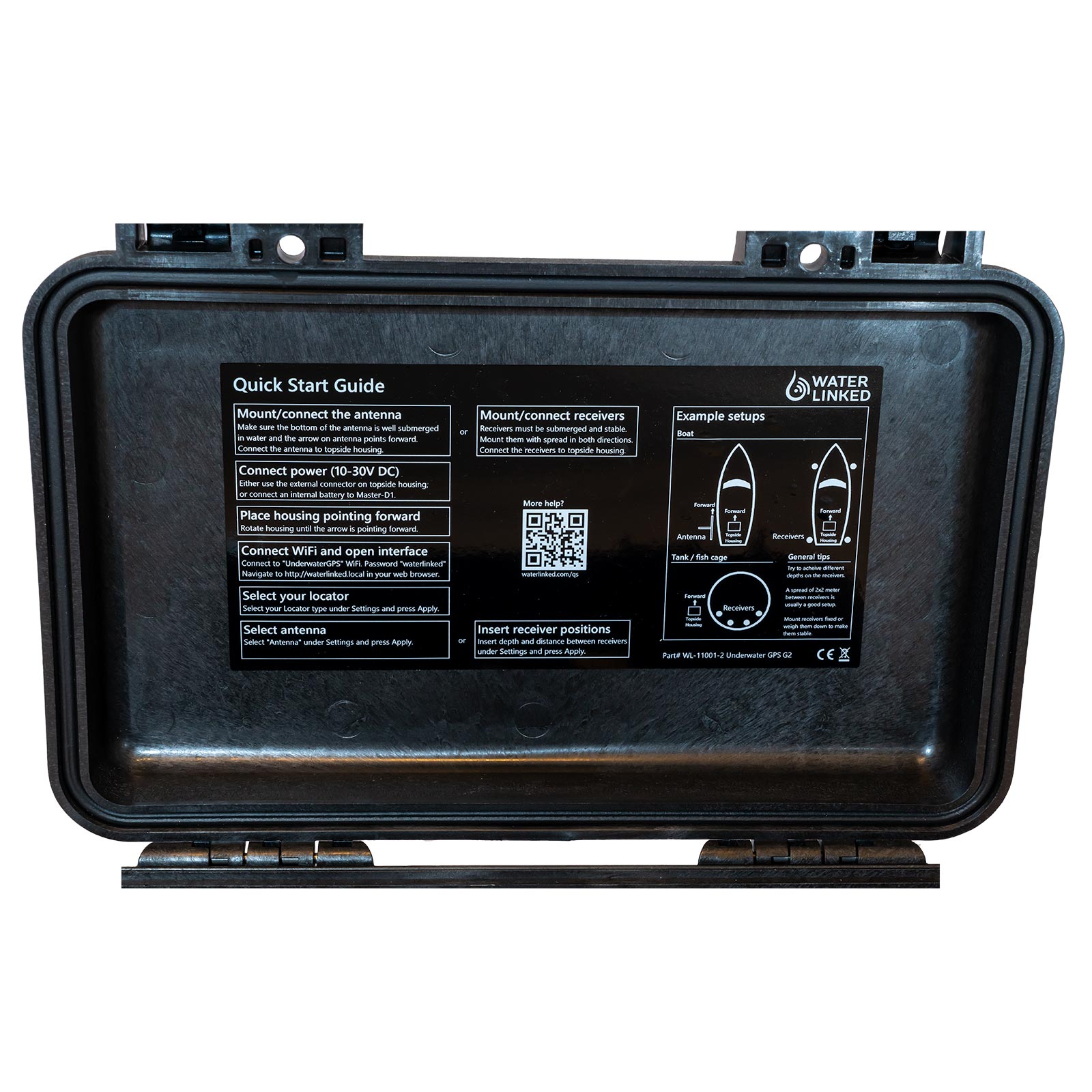
How to set up a Waterlinked GPS?
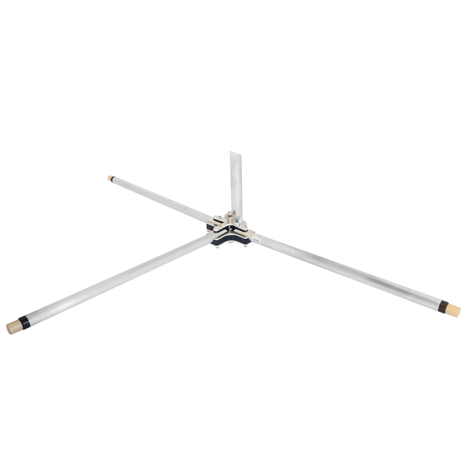
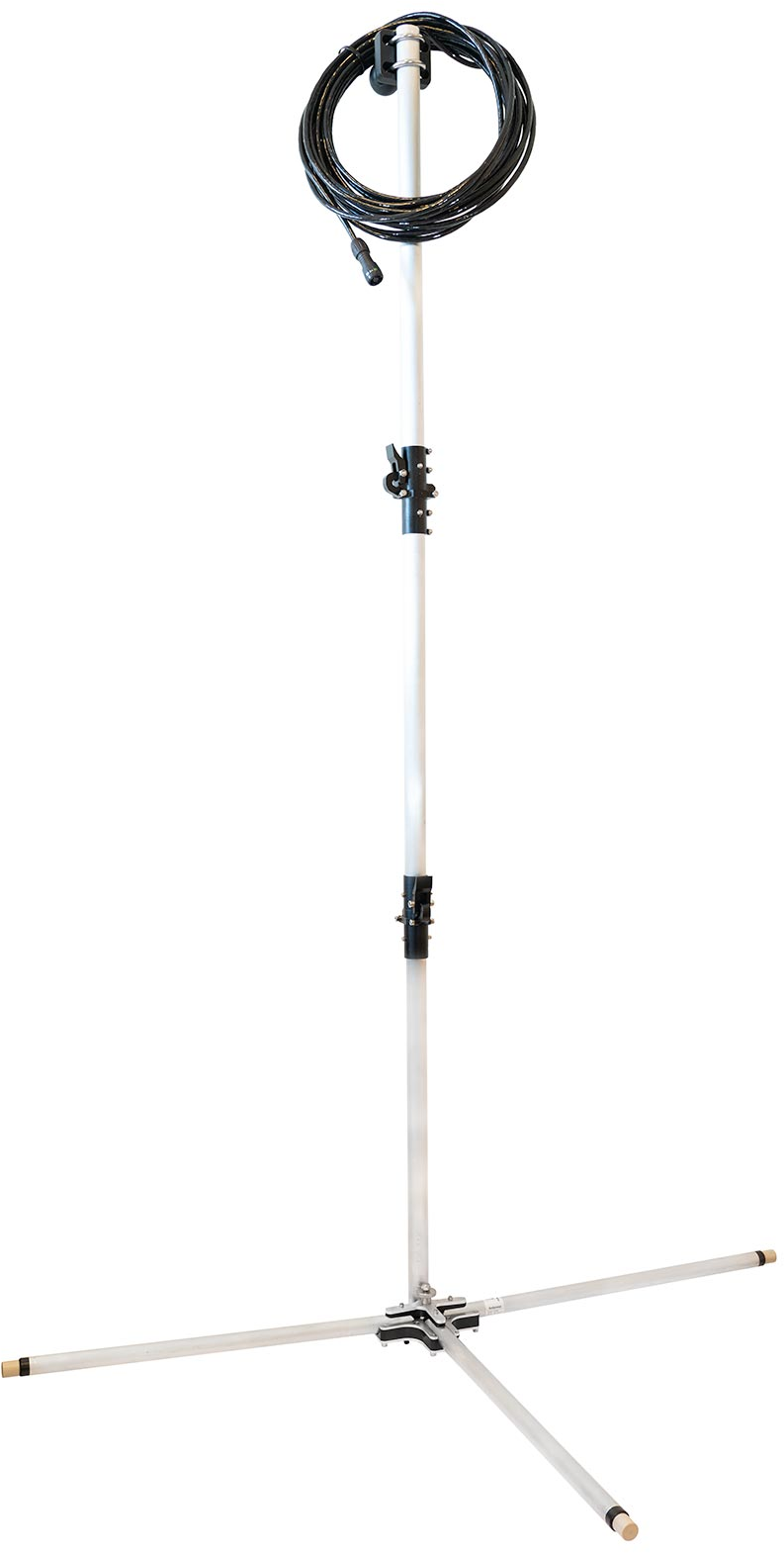
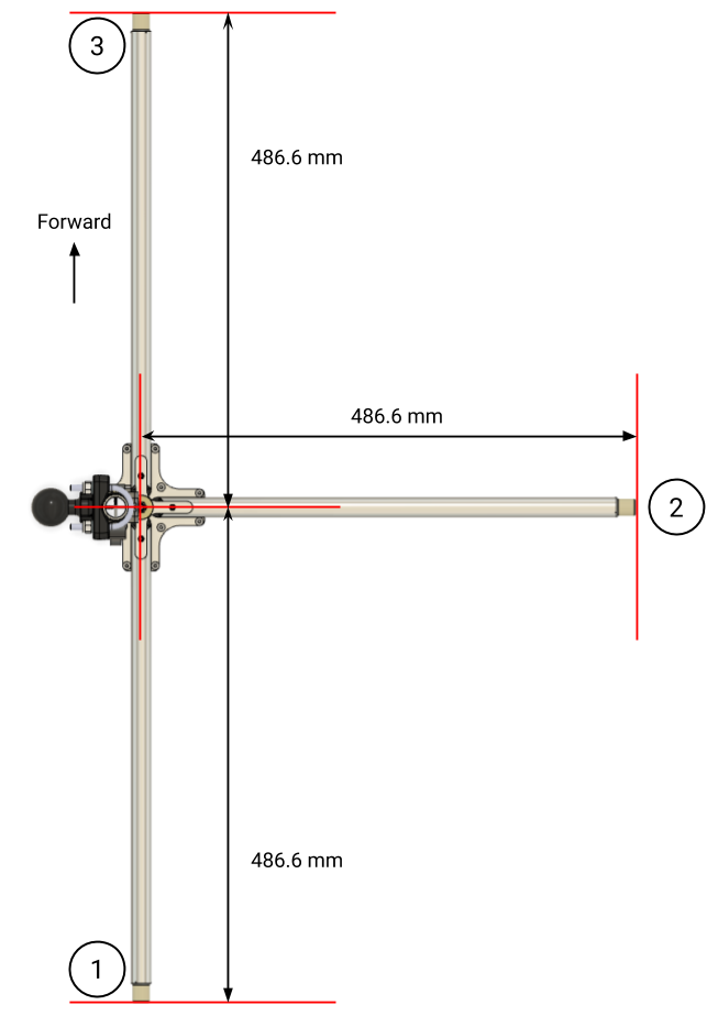
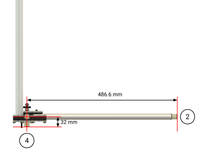
Our Waterlinked GPS is set up with an Antenna (2).
Master (3)Master (instructions)Antenna (2)
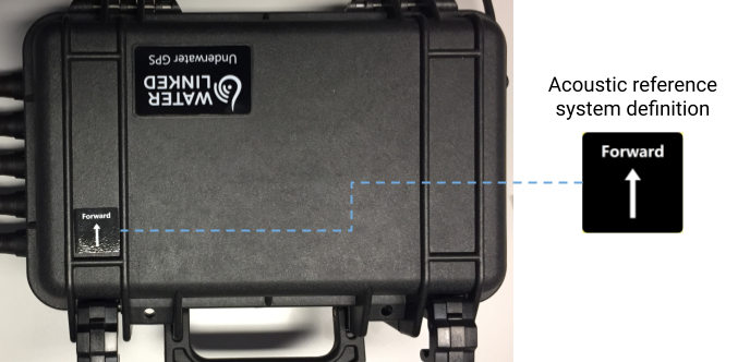
The first thing to do is to attach it properly to the boat, so it will not move. Both the Antenna (2) and the Master (3) have a printed arrow on them, so it is mandatory to point both in the same direction when the Antenna (2) and the Master (3) is attached to the boat.
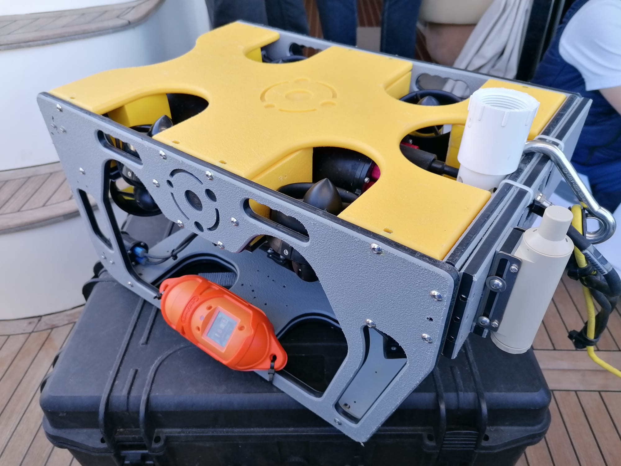
Close correctly the Locator (1), link it with Master (3), attach it to your ROV, and put it in the water (so it will start sending its position):
Locator (1)Locator in ROV (on the right)
Start the pairing process as pointed by the instructions, and once ready, your ROV is prepared for duty.
I did a few basic programs to read data from a Waterlinked GPS and save it in files. Then others can plot the information on your screen using Matplotlib or convert it to GPX or KML format used by Google Maps.
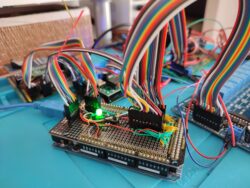
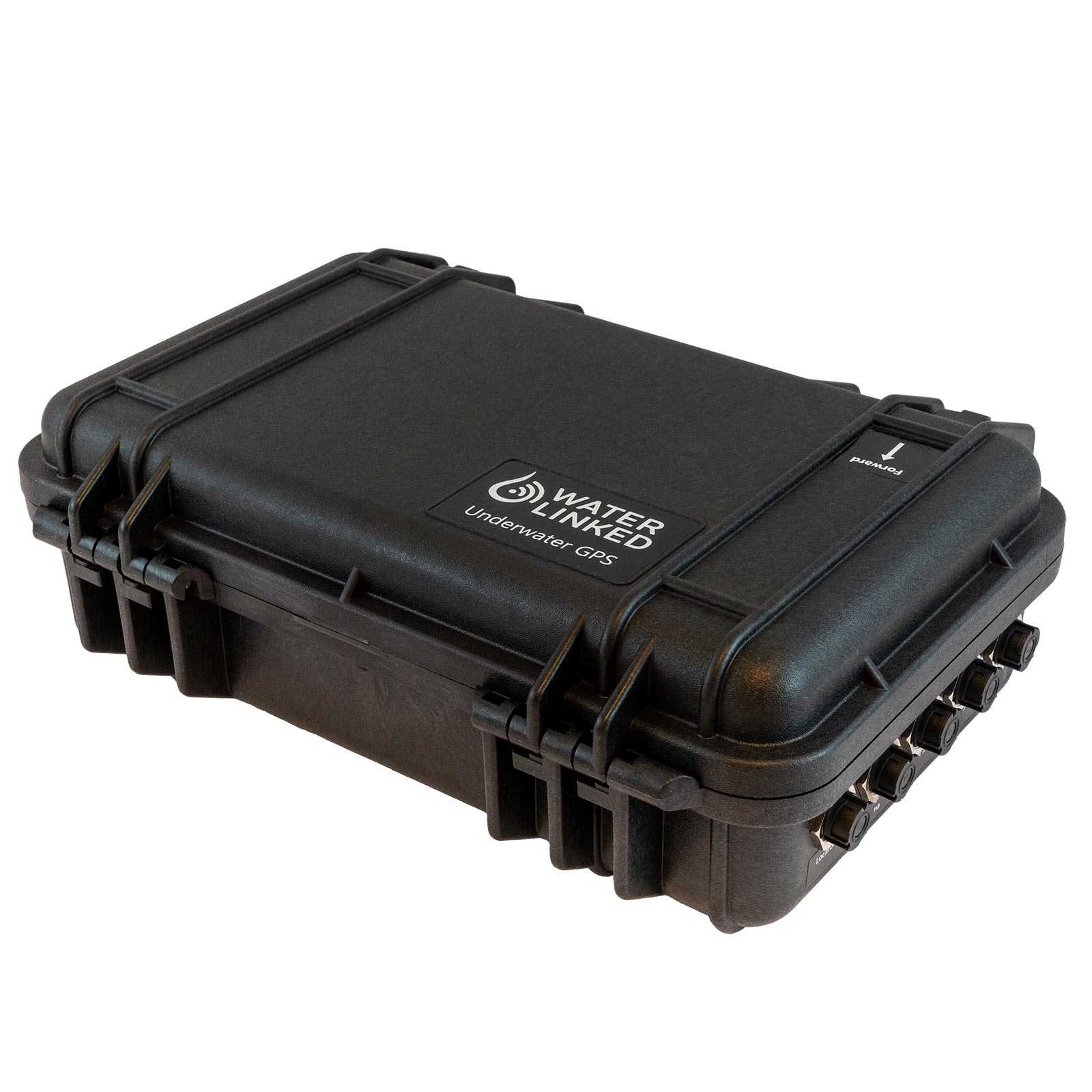
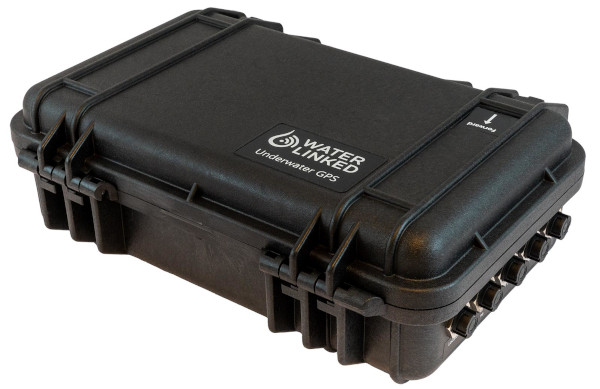
1.- Master (3), a connection box outside the water that will communicate with the computer using a wifi connection (the box works in AP mode with ESSID “UnderwaterGPS” and Password “waterlinked”, the connection box will not deliver a DHCP connection so you must set your own one using 192.168.7.x IP address):
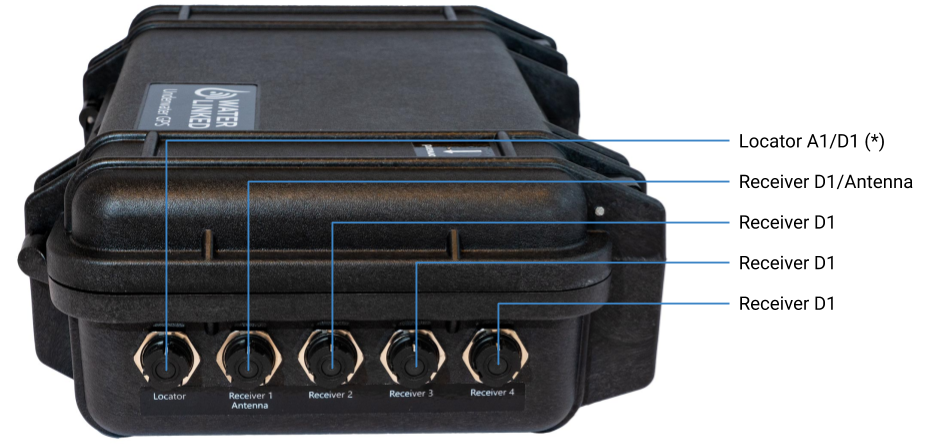
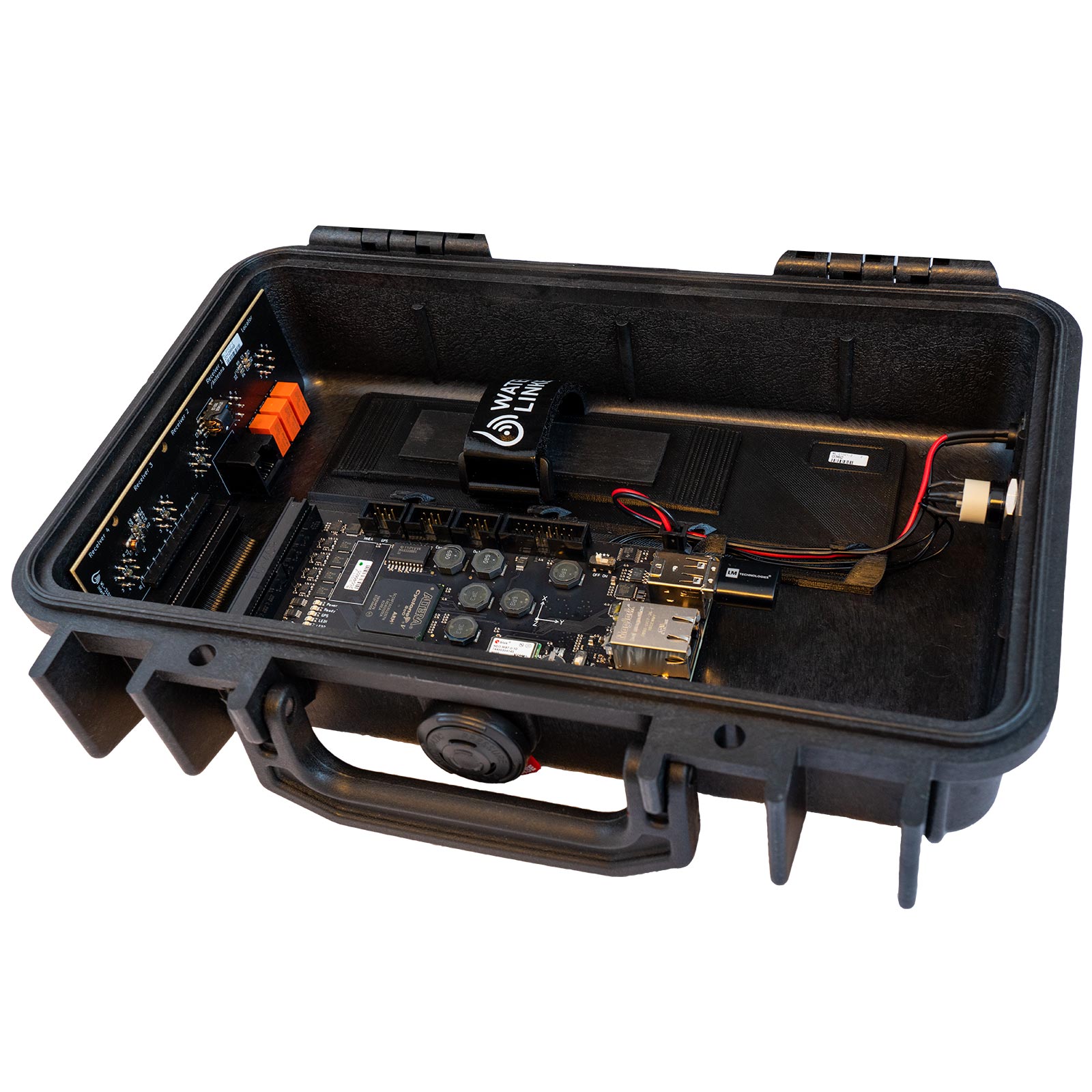
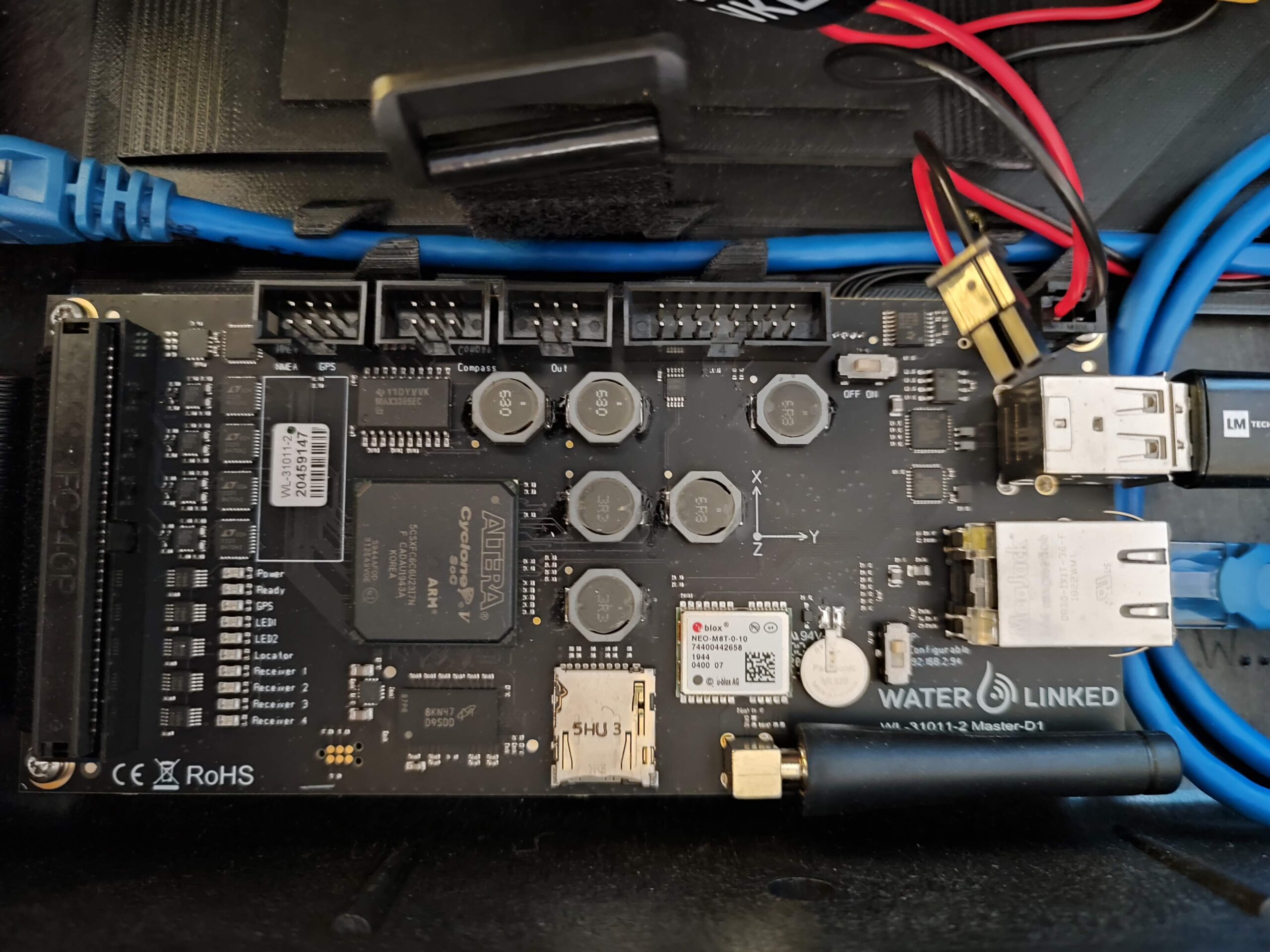
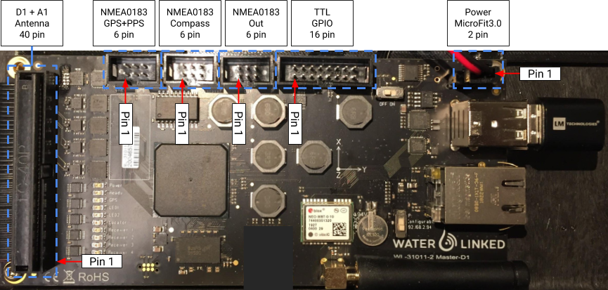
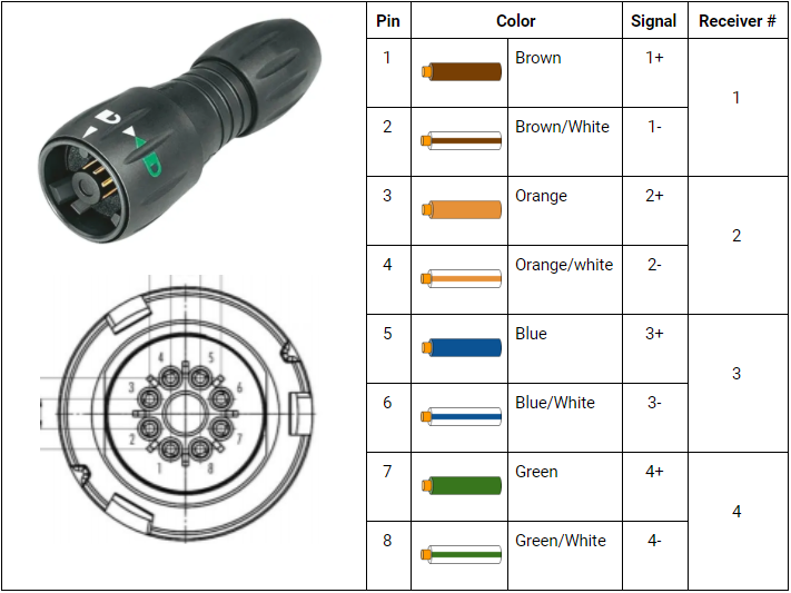
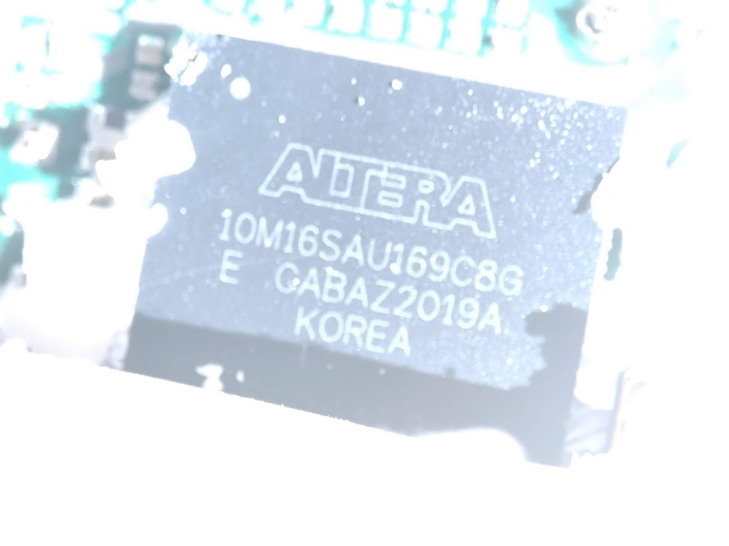
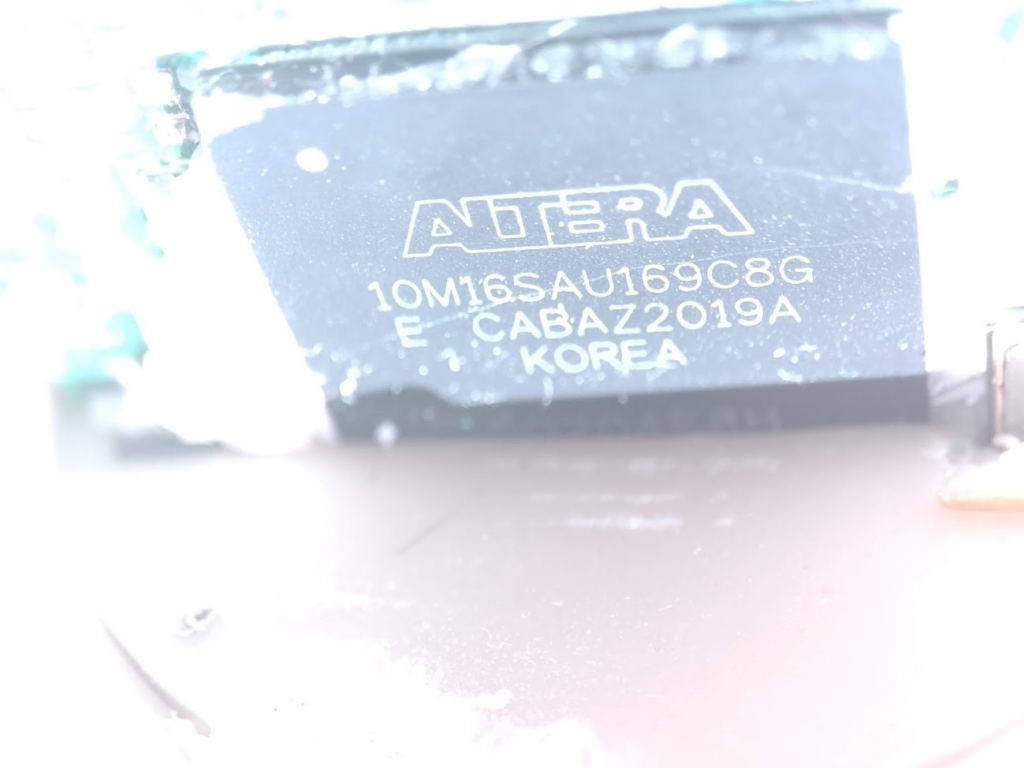
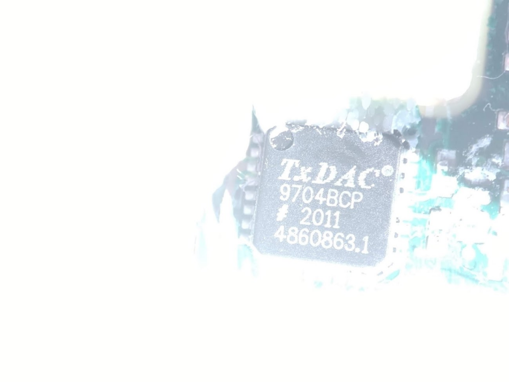
Master (3)Master (3) – There is an arrow on the top of the caseMaster (3) – ConnectionsMaster (instructions)Master (3)Master (3) – MotherboardMaster (3) – Motherboard explainedMaster (3) – GPS Model
40-pin Molex Interface
Signal
Pin
Pin
Signal
Function
GPIO 2*
1
2
GPIO 3
D1 TX+
3
4
D1 TX-
Locator-D1
D1 RX+
5
6
D1 RX-
|
GND
7
8
12 V
Power out
R1 TX+
9
10
R1 TX-
Receiver-D1
R1 RX+
11
12
R1 RX-
|
GND
13
14
12 V
Power out
R2 TX+
15
16
R2 TX-
Receiver-D1
R2 RX+
17
18
R2 RX-
|
GND
19
20
12 V
Power out
R3 TX+
21
22
R3 TX-
Receiver-D1
R3 RX+
23
24
R3 RX-
|
GND
25
26
12 V
Power out
R4 TX+
27
28
R4 TX-
Receiver-D1
R4 RX+
29
30
R4 RX-
|
ANT RX 1+
31
32
ANT RX 1-
Antenna
ANT RX 2+
33
34
ANT RX 2-
|
ANT RX 3+
35
36
ANT RX 3-
|
ANT RX 4+
37
38
ANT RX 4-
|
A1 TX+
39
40
A1 TX-
Locator-A1
* Used to control relays for switching between Receivers and Antenna.
6-pin NMEA 0183 GPS + PPS (not currently implemented)
Signal
Pin
Pin
Signal
GND
1
2
12 V
NMEA GPS TX
3
4
NMEA GPS RX
NMEA GPS PPS
5
6
GND
6-pin NMEA 0183 Compass (not currently implemented)
Signal
Pin
Pin
Signal
GND
1
2
12 V
NMEAS COMPASS TX
3
4
NMEA COMPASS RX
NC
5
6
GND
6-pin NMEA 0183 Out (not currently implemented)
Signal
Pin
Pin
Signal
GND
1
2
12 V
NMEA OUT
3
4
NC
NC
5
6
GND
16-pin TTL GPIO
Signal
Pin
Pin
Signal
GND
1
2
12 V
DNC
3
4
DNC
DNC
5
6
DNC
DNC
7
8
DNC
GND
9
10
PPS OUT
GND
11
12
PPS IN
GPIO 0
13
14
GPIO 1
GND
15
16
3.3 V
Note: TTL voltage 3.3 V (5.0 V tolerant)
2-pin MicroFit 3.0 Power
Signal
Pin
Pin
Signal
GND
1
2
VIN*
* 10 – 30 VDC, 0.7 A (12 V nominal).
2.- Antenna (2), several sensors that will be held underwater near the water line:
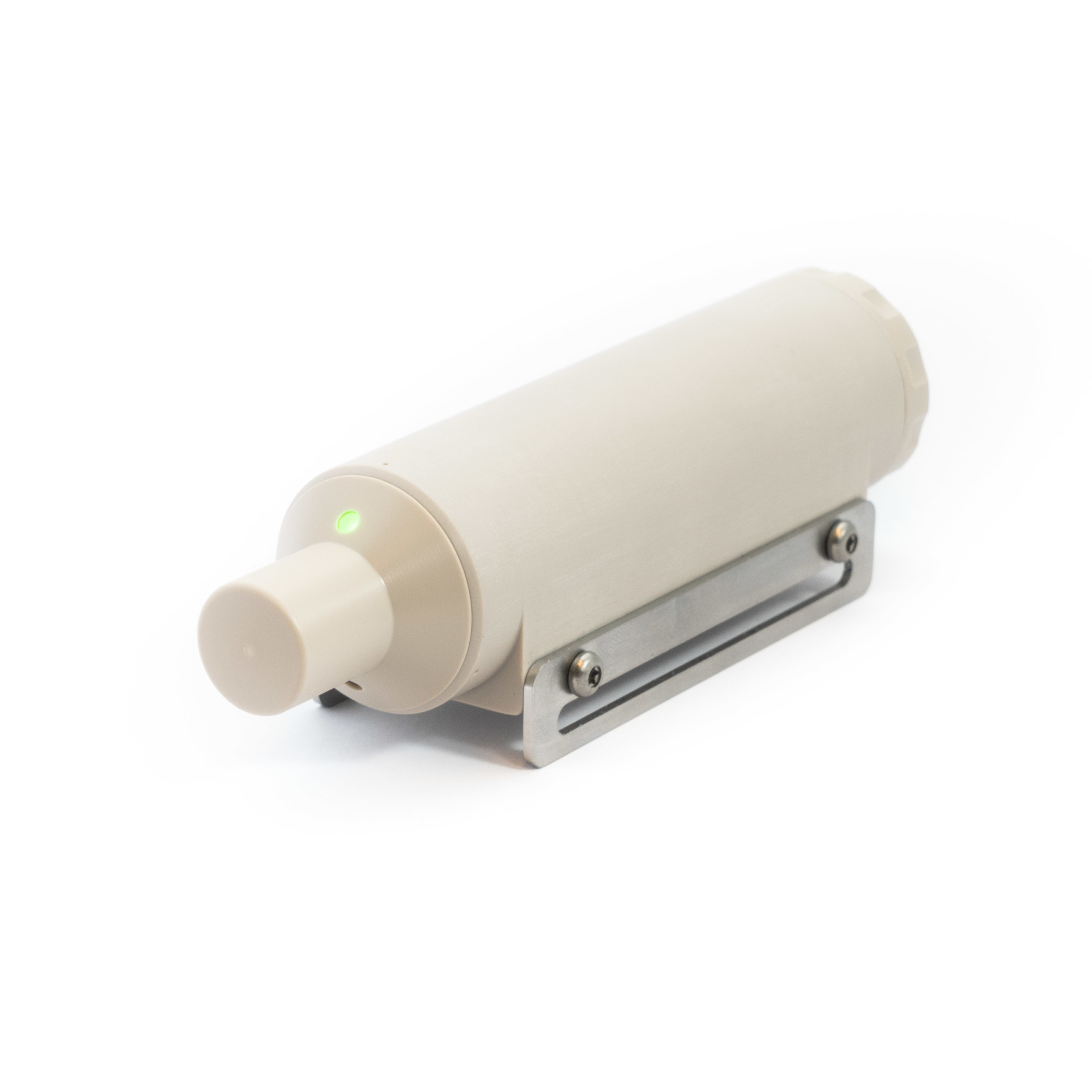
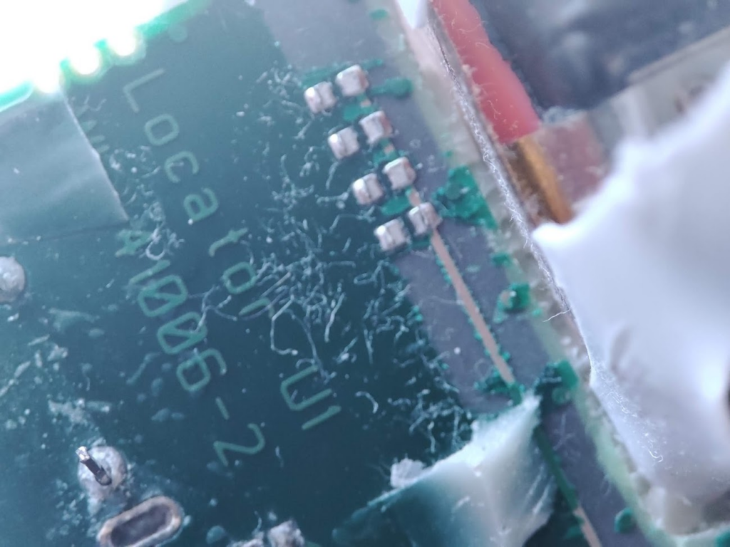
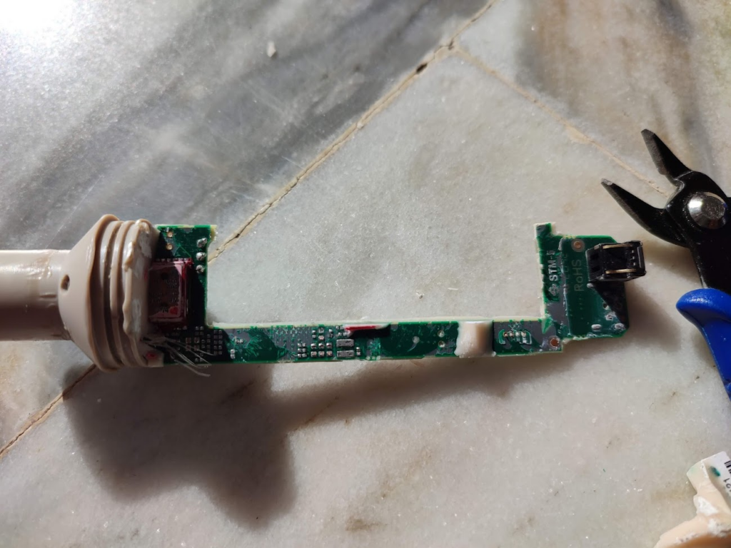
4.- Locator (1): this is one of the most important parts, and we will describe it in detail.
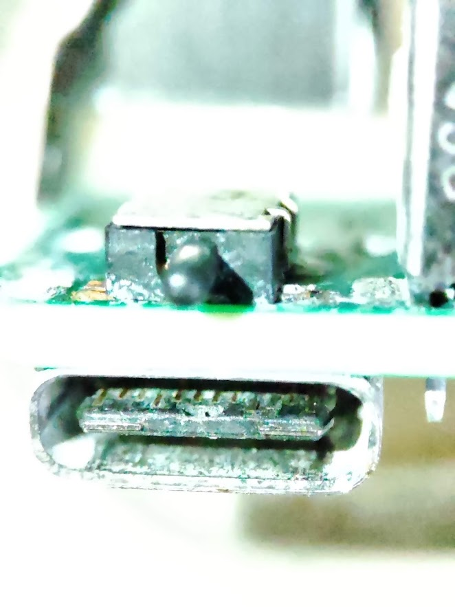
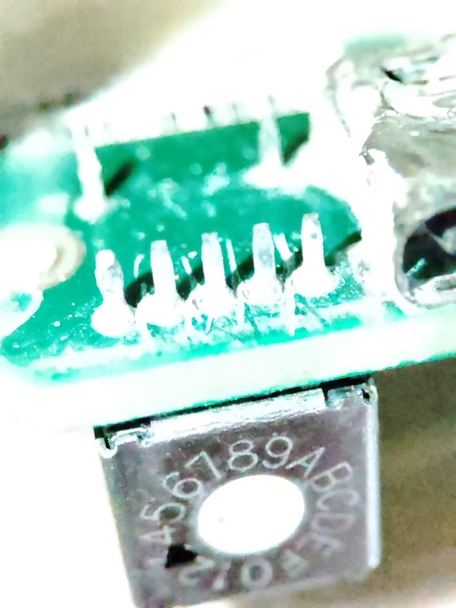
Locator (1) in detail
The external USB-C connector and switch ON button will be pushed when the cap is attached and closed. There is also a potentiometer it may be used for channel configuration:
Switch ON/OFF button + USB C
Potentiometer
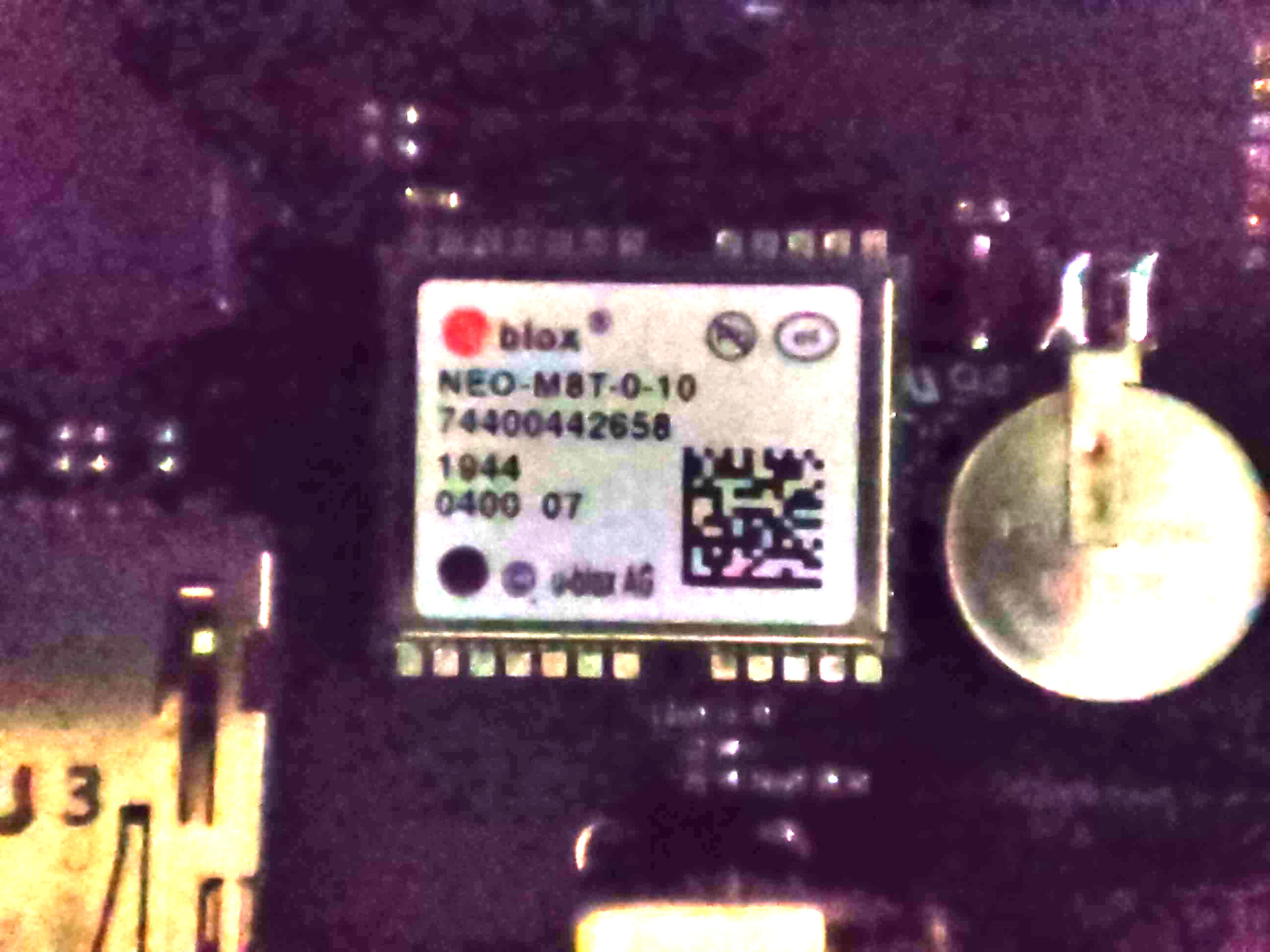
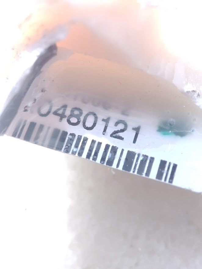
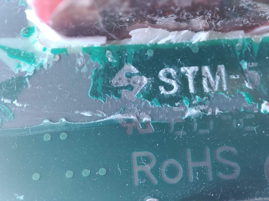
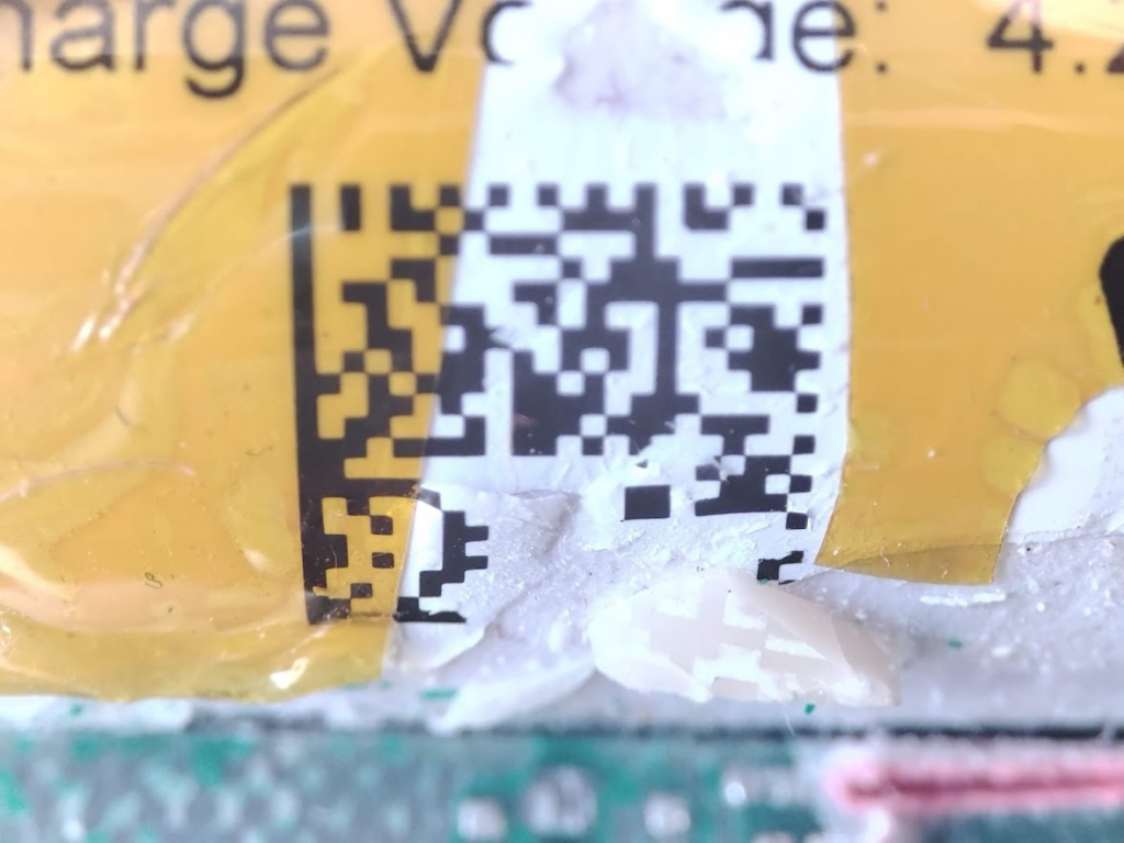
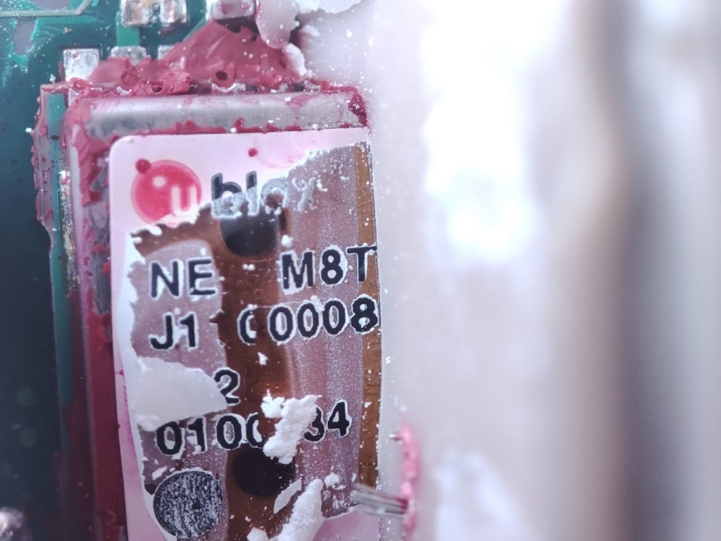
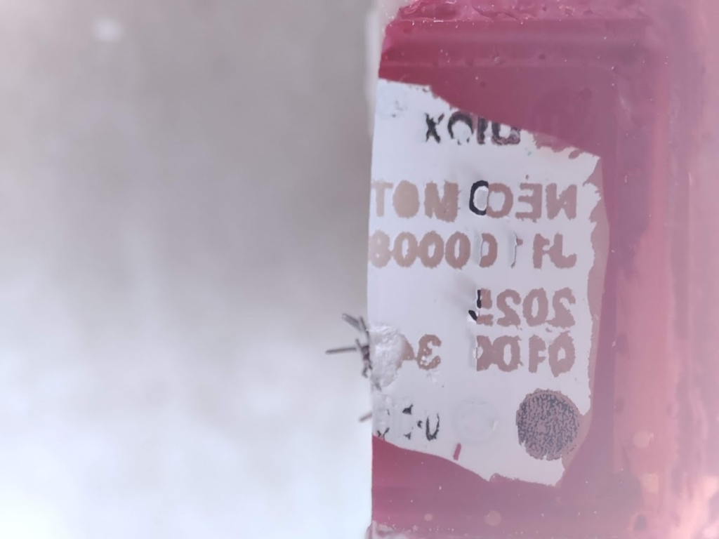
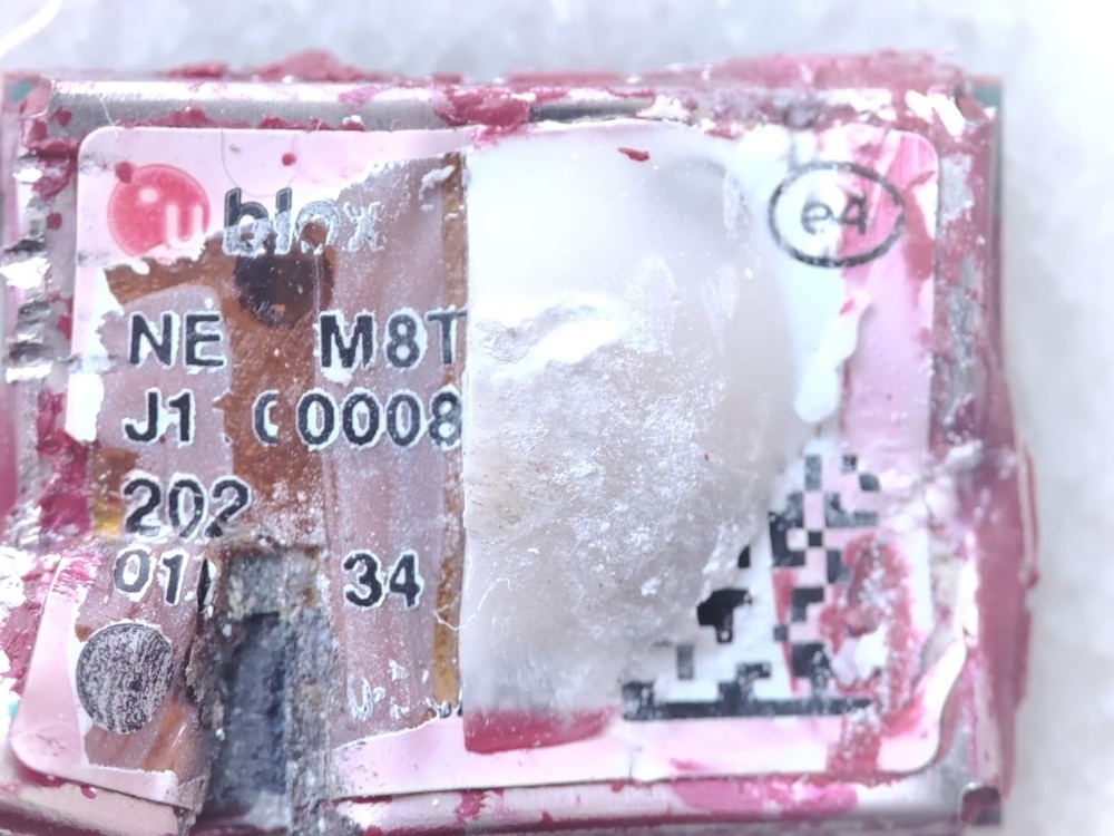
There is a serial number on the motherboard. I believe this is the serial number of the sensor itself when configured by the manufacturer:
Serial Number
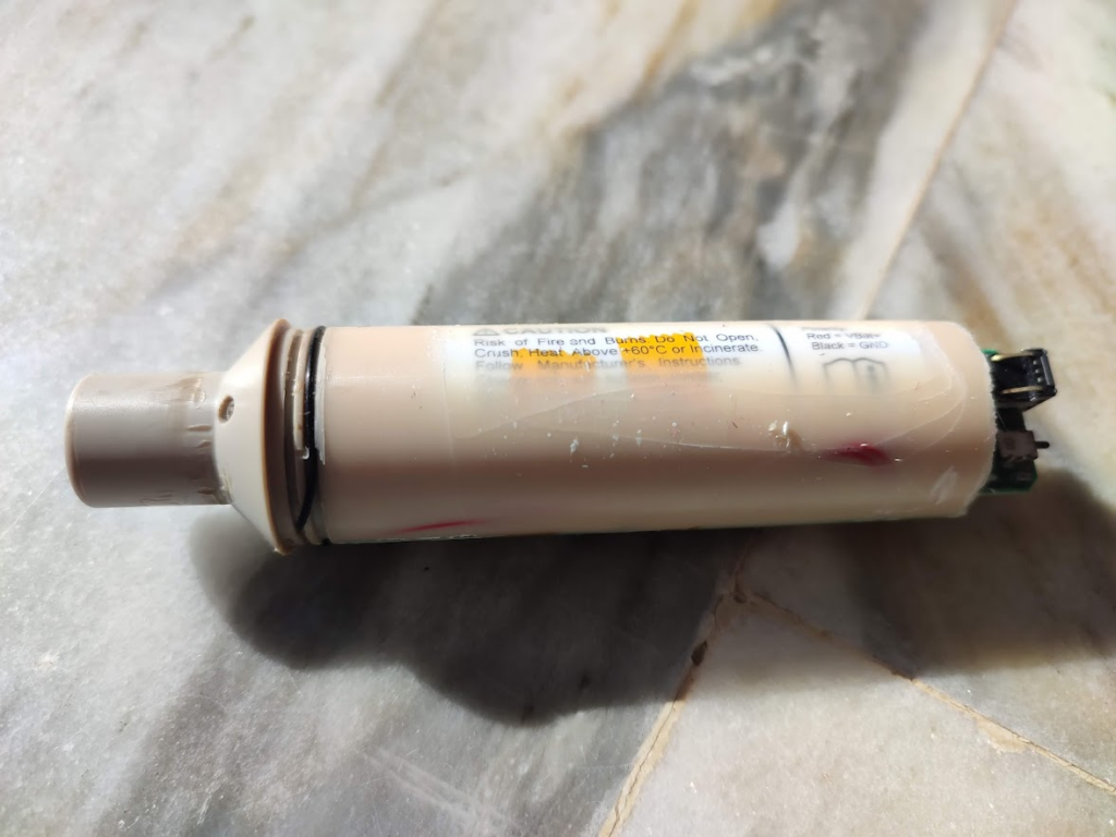
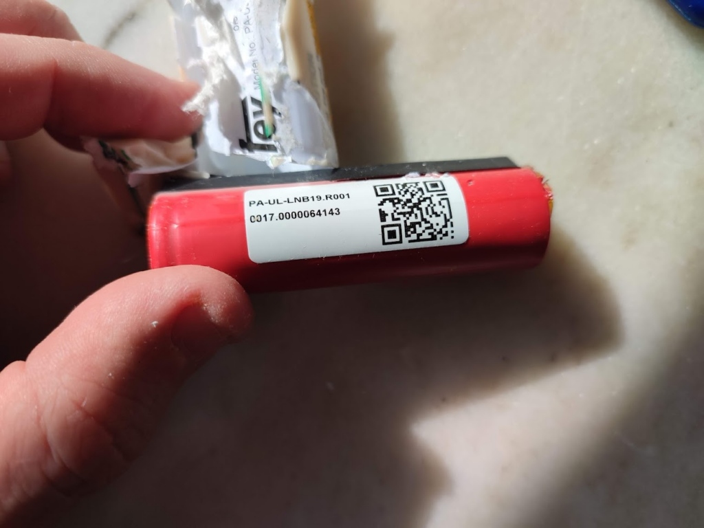
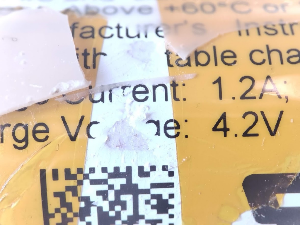
The entire sensor is enclosed in a tube filled with epoxy glue. After removing the cover (tube), we can see the battery:
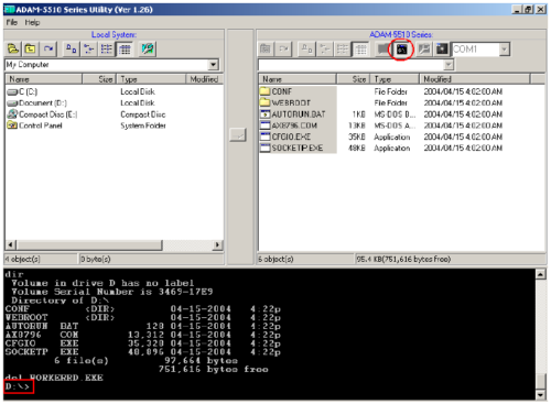
I got some days ago the new ADAM 5510E TCP. It is nicer than ADAM 5000TCP that we showed in August. We will not show photos of it this time because it looks the same as its brother ADAM 5000TCP. What makes the new ADAM better? Mainly that we can get inside to program it with C. What is it inside? How to get inside? Through the RS-232 port for programming like this screenshot: What software is included with it? What can I do with it?: You can program yourself in […]
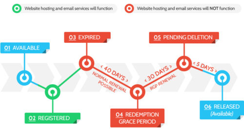
En este artículo hablamos del ciclo de vida de un dominio. El nombre de dominio está registrado o renovado. Los nombres de dominio pueden estar registrados o renovados por un período de 1-10 años de tal manera que no atraviesen el período máximo permitido desde la fecha de registro o renovación. El nombre de dominio caduca, comienzo del […]