In my last post, “Get your hardware for Arduino Underwater ROV”, I described most of the hardware I use to build Alioli ROV and how I plan to use it. In this post, I will show how the hardware interconnects with each other and the boards I have built.
During the process of building Alioli ROV, I went through several changes, most of them because I learned from the experience and improved the process of soldering and implementing boards. For example, I started building my boards in the latest integrations because it made it easier to keep the table clean and more comfortable since I didn’t have so many cables on my table.
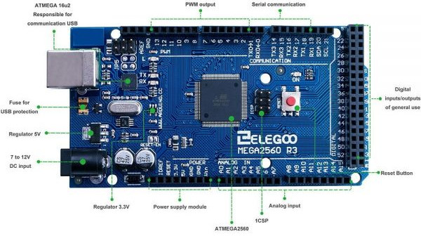
The mainboard for the Alioli ROV is an Arduino Mega 2560 R3:
Arduino Mega 2560 Rev3
Power supply
The power I will need for Alioli ROV is:
Arduino works at 5V
Motors work at 12V
The clock and some sensors work at 5V
After getting the gyroscope and pressure sensors, I discovered they work at 3.3V.
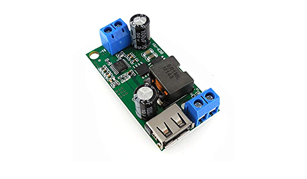
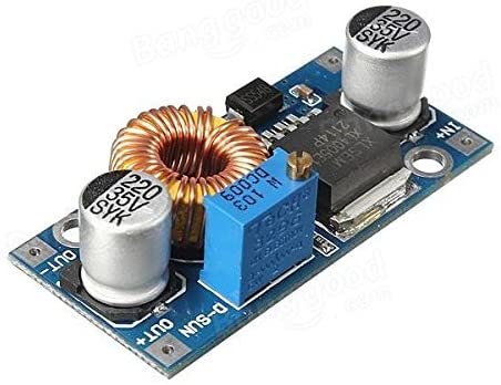
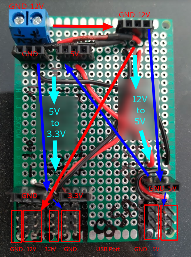
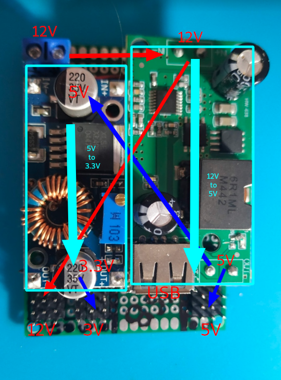
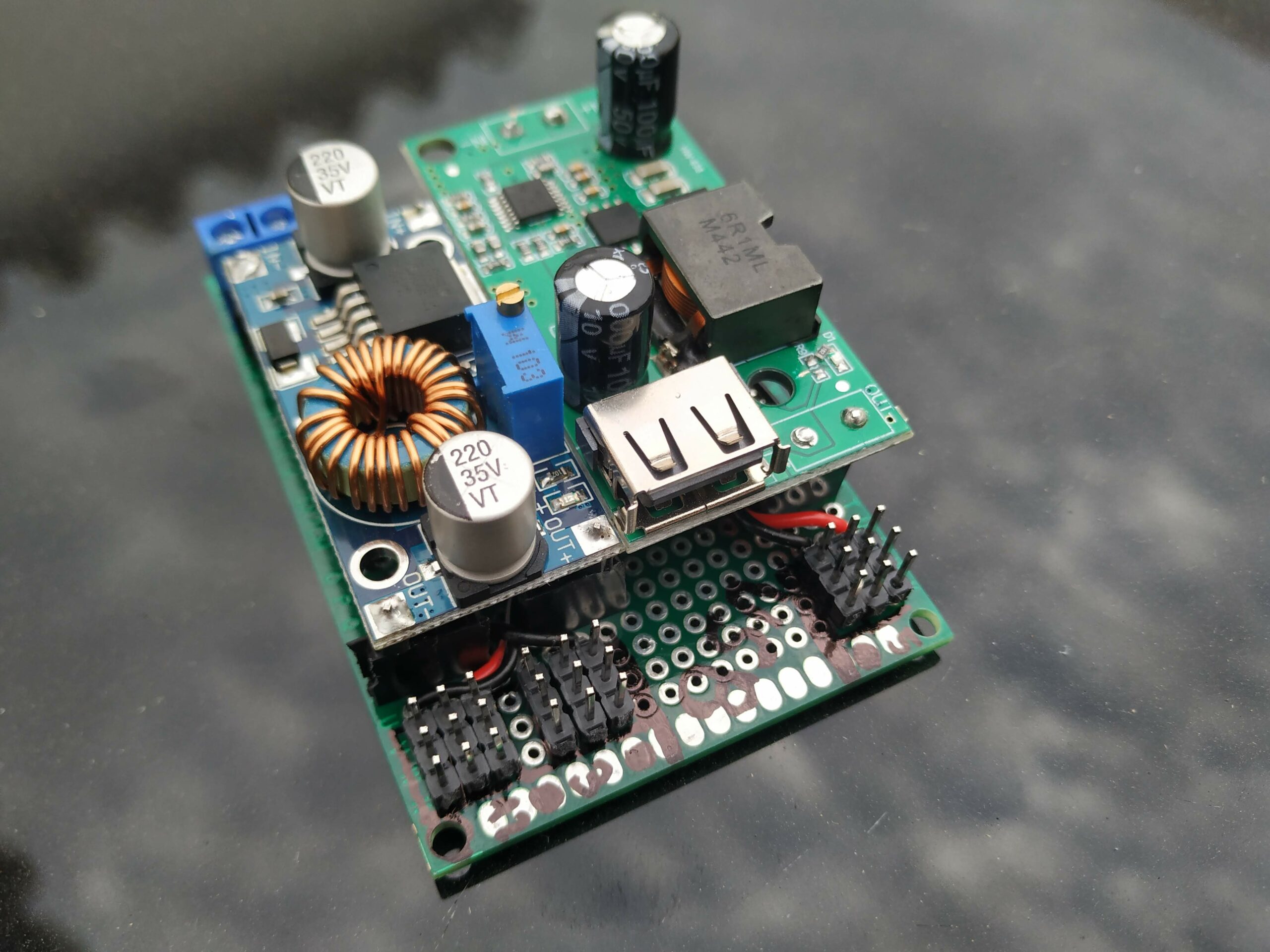
I need 12V (motors), so I use a Voltage Stabilizer from 12V to 5V (HW-638) and a Voltage Converter from 5V to 3.3V. Engines will get their power straight from the battery since the rest of the system will get their power from the Voltage Stabilizer. In this way, I am protecting the circuit from the noise of the motors when they start and stop. After the voltage stabilizer, it will be a Reducer Regulator Module from 5V to 3.3V to provide 3.3V to any circuit that needs it.
HW-638 5V Voltage Stabilizer 12V to 5VVoltage Converter DC-DC 5-32V to 0.8-24V
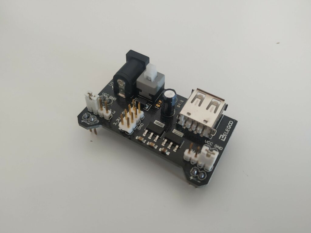
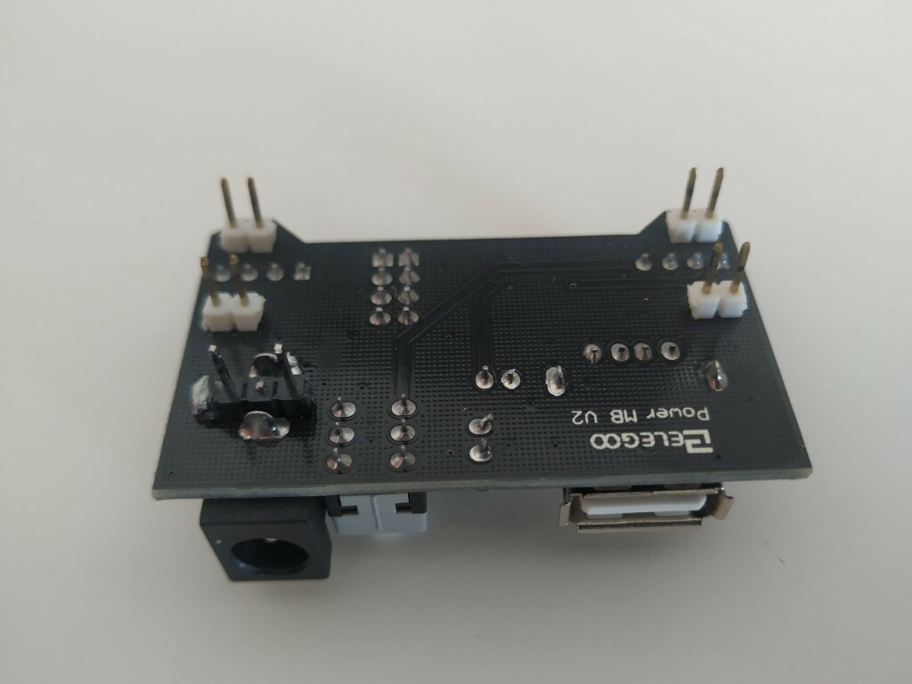
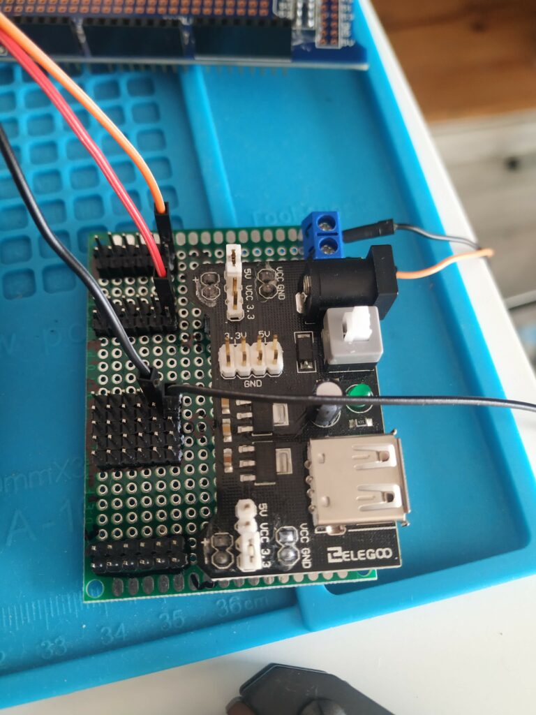
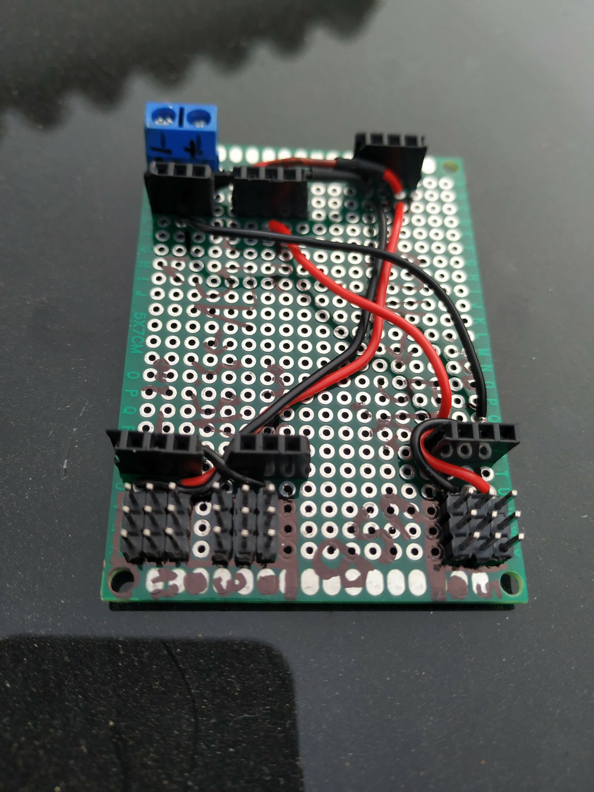
I decided to build 2 boards: the first is to reuse the Arduino Power Supply Module from the kit I bought. Hence, it provides me with several pins at the same voltage level, and I can also use the switch to power on and off during tests. The second board is the one I will use when the testing phase finish.
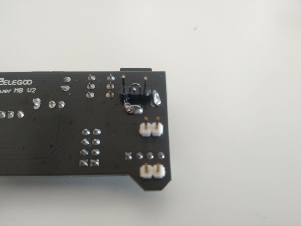
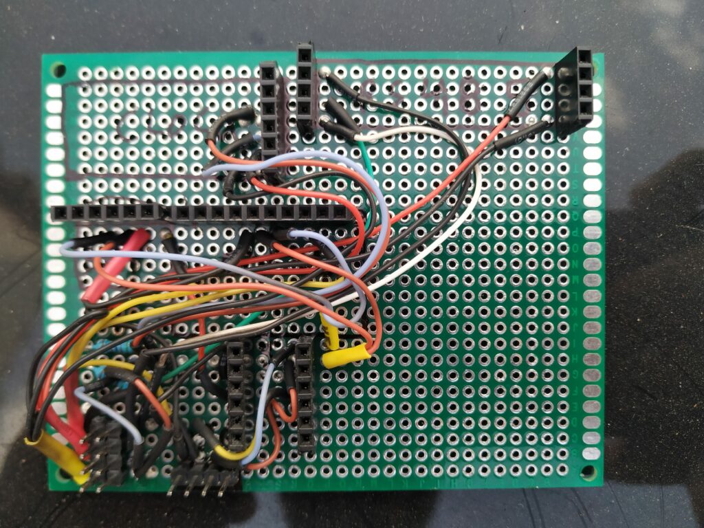
Arduino Power Supply ModuleSoldered a pair of pins to the power connectorA closer look at the new soldered pinsThe board where I will attach the Arduino Power Supply ModuleA general view of the Arduino Power Supply Module attached1st board for Arduino Power Supply ModuleAlioli ROV Power Supply BoardStabilizer + Converter attachedAlioli ROV Power Supply Board2nd board Alioli ROV Power Supply Module
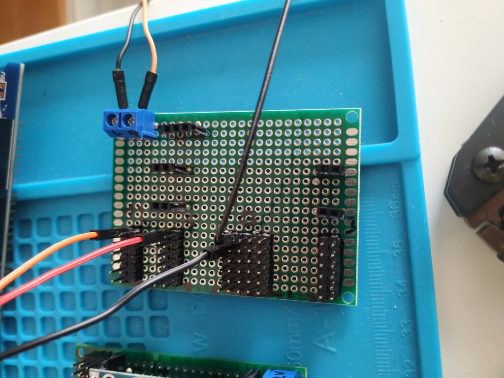
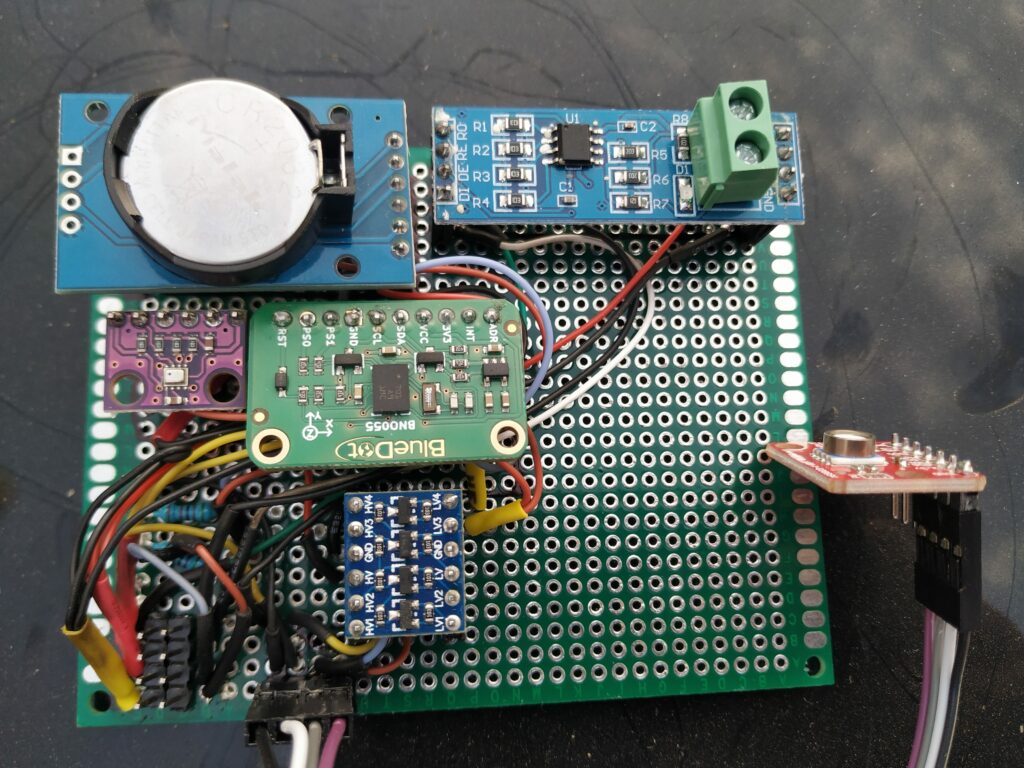
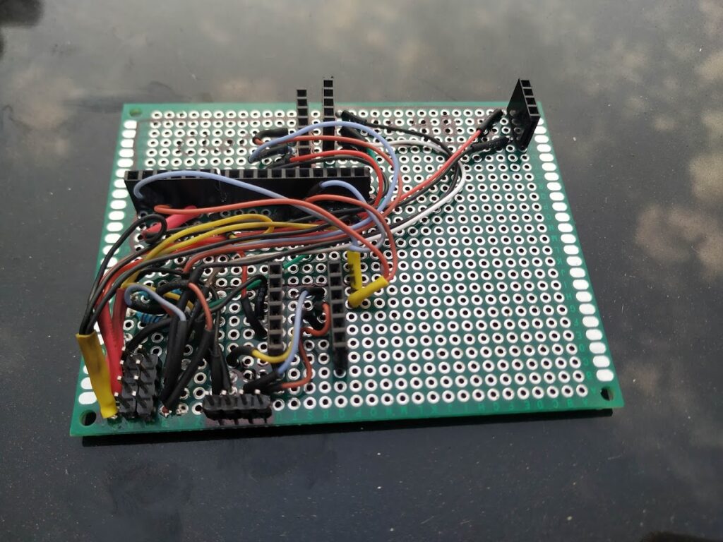
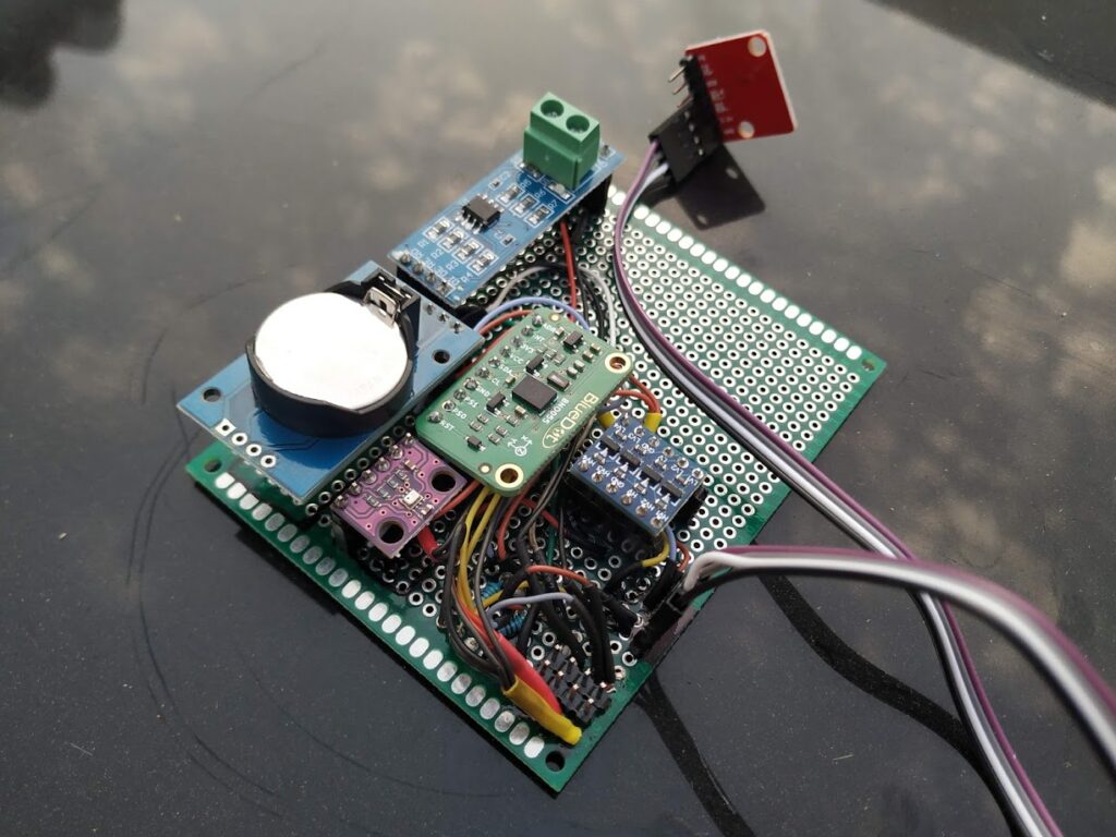
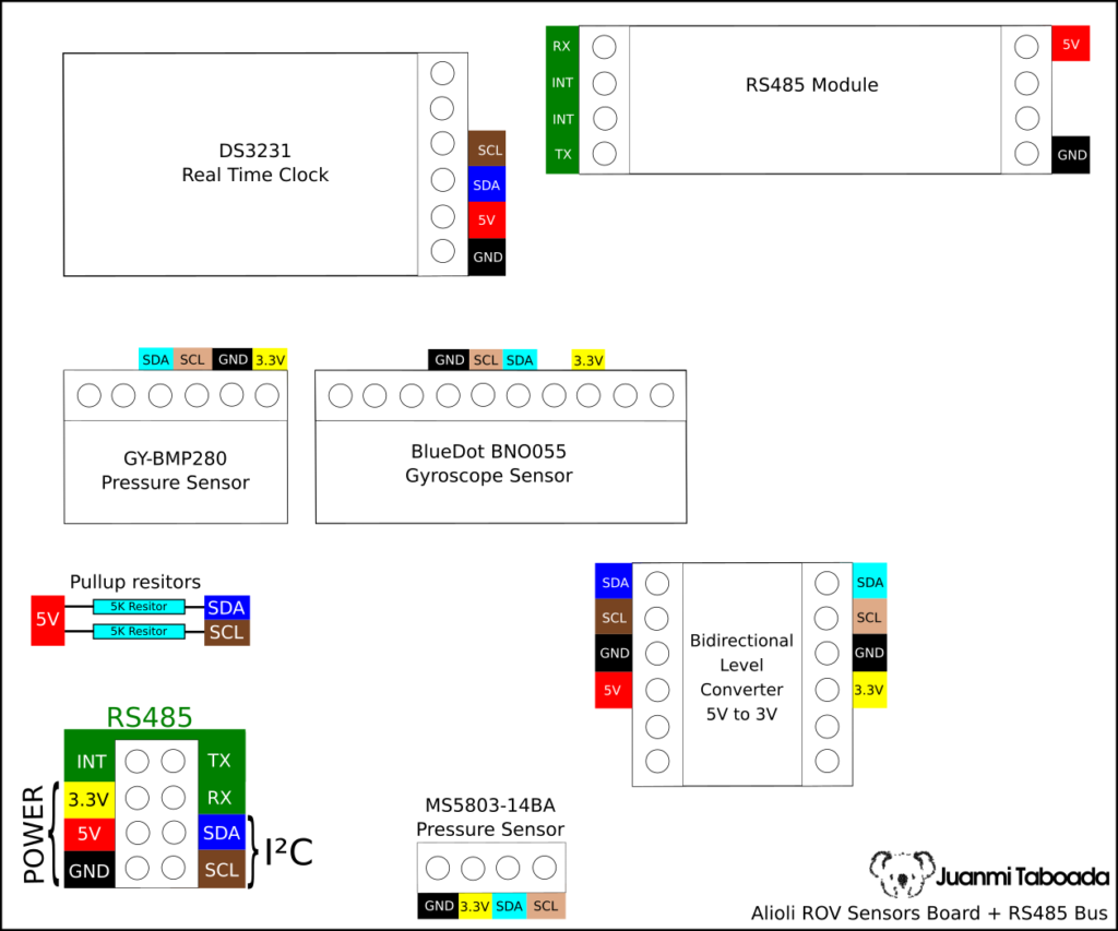
I²C + RS485 board
Many of my modules work with I2C, and because of that, I decided to make a board just for all of those. In addition, I thought it was a good idea to attach the RS485 communication board to compacter the final result. To build this board, I used wires (30AWG 0.05mm²) with a silicone cover, making it easier to sell and manage. Some of the sensors work at 3.3V, so I have used a level converter to communicate 3.3V sensors with the rest of the bus at 5.5V (you can learn more about level shifter here “How a Bidirectional Logic Level Converter works? Logic Level Shifter“). WARNING: watch out, SDA & SCL are in different colours to show different bus voltages:
Next post
During these days, I will get Prototype Boards for Arduino Mega 2560 R3 to prepare buses and test everything with the existing software. In the next post, I will publish the rest of the hardware I have been working on, and I will interconnect everything, the “Learn how to Build an Engine Controller for your Alioli Submarine UAV Drone“.
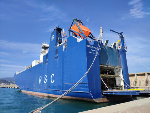
I will tell you about my experience repairing a cargo ship as a naval Engineer. Some months ago, you could read in the local newspaper Málaga Hoy that a large cargo ship was approaching Málaga after a major accident it had suffered in its front part. It was the cargo ship Integrador with a Panamanian […]
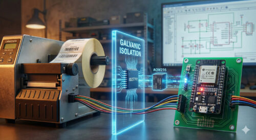
The Challenge I recently took on the challenge of modernising a Labelmate PM-300-CS dispensing machine (Internal Mother Board). Ideally, I wanted to control this industrial hardware from my computer, so I decided to interface an ESP32 microcontroller. However, there was a major hurdle: the machine operates on 15V logic with noisy motors, while the delicate ESP32 operates […]